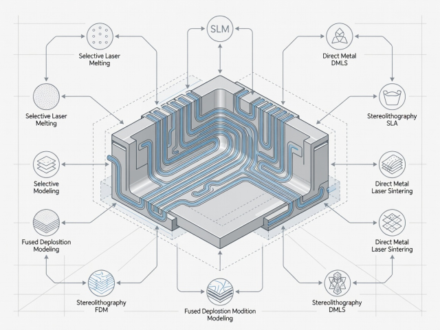
Write the production intent first
Define the part’s job before discussing equipment. Record loads, temperatures, chemical exposure, mating features, expected life and annual demand. Separate mandatory requirements from preferences. A housing that must seal against a machined face presents a different problem from a handling fixture whose main requirement is stiffness. Both might fit the same printer, but they should not inherit the same process plan.
The terminology in ISO/ASTM 52900 provides a useful starting point for discussing additive process families. It does not make those families interchangeable. A qualified material, machine and parameter combination must still be connected to a particular design and acceptance route. Ask suppliers to describe the finished condition they are quoting, rather than simply naming an alloy and a process.
Powder bed fusion: detail with access constraints
Laser powder bed fusion can produce metal components with detailed features and internal passages. The surrounding powder supports the geometry only in a limited sense: metal parts often still need structures for thermal management and restraint. Orientation influences supports, surface condition, build duration and the direction in which properties are evaluated.
Electron beam powder bed fusion uses a different energy source and process environment. Its thermal conditions and material options should be assessed on their own merits. For either route, plan how powder leaves internal spaces, how the component separates from the plate and how critical surfaces can be reached. An enclosed cavity that traps powder is a production problem, not merely a drawing detail.
Directed energy deposition: build near the final shape
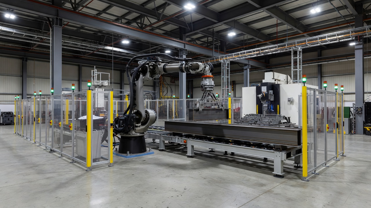
Directed energy deposition introduces material while a focused energy source creates a melt pool. Feedstock may be powder or wire. Wire arc additive manufacturing is a commonly used description for wire-based, arc-driven deposition. These routes can suit large near-net-shape structures, repairs or added features, subject to material compatibility and qualification.
The deposited bead is generally not the final precision surface. Allow machining stock, accessible datums and workholding features. Large structures also need practical plans for heat management, distortion measurement and transport between cells. A deposition robot’s reach is not the same thing as a guaranteed usable part envelope: positioners, shielding arrangements and collision avoidance consume space.
Polymer routes: distinguish parts from tooling
Large-format material extrusion often uses pellet feedstock and can be useful for tooling, patterns and large fixtures. Fibre-filled compounds may improve stiffness or dimensional behaviour, but they do not remove the influence of bead direction, voids or interlayer bonding. Service temperature and thermal expansion are especially important when a printed tool will see a curing cycle.
Polymer powder bed fusion can offer a different balance of geometry and batch packing. Selective laser sintering and multi-agent powder fusion systems should be evaluated using the actual material, refresh policy and required part condition. Do not transfer a property value from one polymer grade or process directly into another production route.
Binder jetting moves important work downstream
Binder jetting joins powder with a binding agent during printing. In metal routes, the printed green part usually requires subsequent debinding and sintering. Fragile handling and predictable shrinkage become central production considerations. Furnace capacity, support strategies and dimensional compensation can determine whether an apparently fast printing stage produces a dependable finished component.
This is why comparing only build time is misleading. A route with fewer in-chamber thermal stresses can still require extensive downstream control. Ask how the supplier validates density, dimensions and material properties after the complete thermal cycle, and whether your geometry falls within the demonstrated production envelope.
Use facilities as learning references, not universal proof
The Manufacturing Technology Centre in Coventry, the University of Sheffield’s Advanced Manufacturing Research Centre, and Oak Ridge National Laboratory’s Manufacturing Demonstration Facility provide documented examples of manufacturing research and industrial collaboration. Their work can help a team understand integration challenges. A successful demonstration elsewhere does not establish that your component is qualified, economic or ready for serial production.
Finish the selection exercise with a short route specification: feedstock, process family, orientation assumptions, finishing sequence and acceptance evidence. Compare this with machining, casting, forging or fabrication against the same requirements. Additive is strongest when a specific geometric, supply or functional advantage survives that complete comparison.